A 10MHz (double) oven controlled crystal oscillater STP2145A from CMAC is used as 10 MHz reference. The output is 7 dBm with a very good short term stability is , and a tuning range of +/- 2.5Hz. I use a Jupiter GPS module of which the 10kHz output signal is used in a slow pll. The 10MHz is divided to 10kHz in 2 74HC390’s and fed in to a phase comparator 74HCT4046 with the 10kHz from the Jupiter. The output is lowpassed an tunes the OXCO to exactly 10MHz.
The results are quite good, the local 3 cm beacon PI7SHY on 10386.037 MHz, which also is GPS locked, is received exactly on frequency. The beacon is locked to GPS following the design of VE2ZAZ.
First I wanted to lock my 23cm transverter to the 10MHz standard. Since my transverter uses 2 meter as IF, the LO is 1152 MHz, derived from a 96MHz crystal oscillator, which is multiplied to 288, 576 and finally 1152 MHz.
To lock 96MHz to 10MHz is done in a very simple way using a U664B and 3 TTL chips:
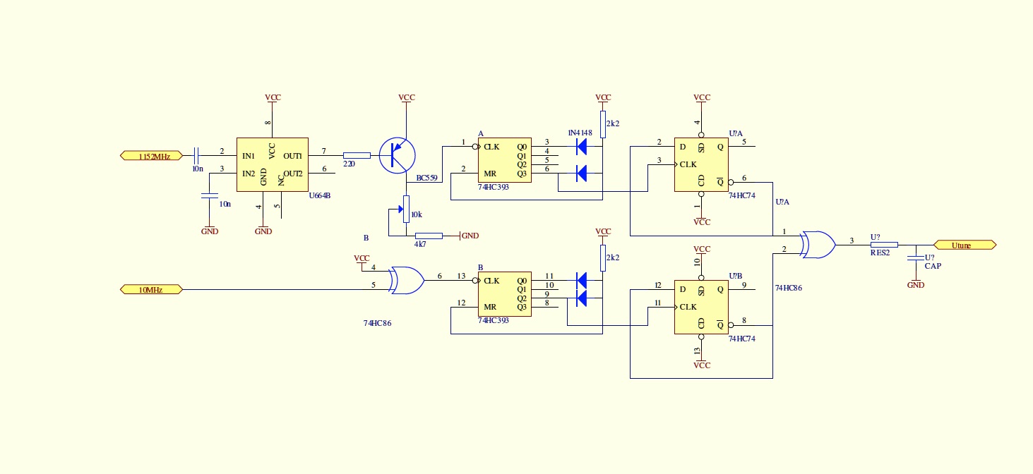
The 1152 MHz is divided by 64 in a U664B to 18 MHz, which is then divided by 9 in half a 74HC393 followed by a divide-by-2 to get a 50% duty cycle. The ECL-output of the U664B is converted to TTL with a PNP transistor. The pot is used to set the triggerpoint. The 393’s are reset with a OR-gate consisiting of 2 (or more) diodes. The upper 393 half counts until 9 where it is reset because only then both outputs, and thus the Reset-entry, are high. In a similar way the lower 393 half divides the 10 MHz by 5 (by counting to 5), and ten in a flip-flop again by 2 to make a symmetrical 1MHz signal for the phase comparator. This is an exor in a 74HC86. The output of the phase comparator is low-passed in a simple RC filter consisting of 1k and 100n. The resulting tuning voltage tunes a BB105 in the crystal oscillator. The BB105 is coupled to the oscillator with a 5p6 capacitor. Take care that the tuning range of the oscillator is enough.
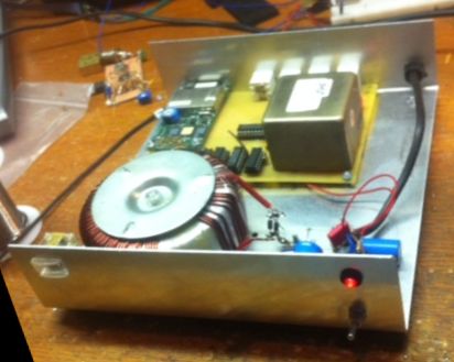
I build the design dead-bug in a small tin box.
As described the locking of 1152 to 10MHz can be done rather pragmatic with a couplke of TTL-chips. Locking other LO frequencies to 10MHz is in general less straightforward because there is no simple relationship between the LO-requencies, available prescalers and the reference frequency derived from 10MHz, unless more complicated dual-modulus prescalers are used. Therefore a general design was developed, also as simple as possible.
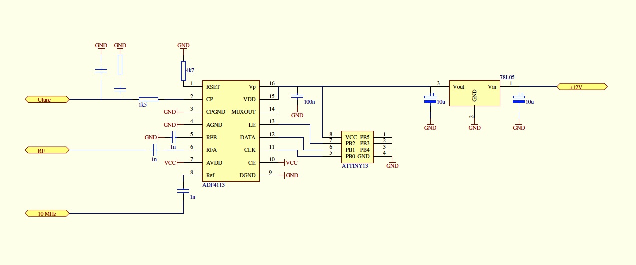
I use a ADF4113 PLL which operates up to 4 - 5 GHz, so any LO for example for 13 cm (2176 for IF 2 meter), or 3 cm (2556 MHz) are easy to connect. The pll is very versatile but needs to be programmed when initialized. I use an Atmel ATTINY13 for this, a simple 8 pins microcrontroller.
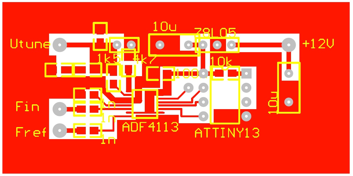
A small pcb sized 60x 30mm is designed for the few (SMD) components. Click for pdf real-sized.
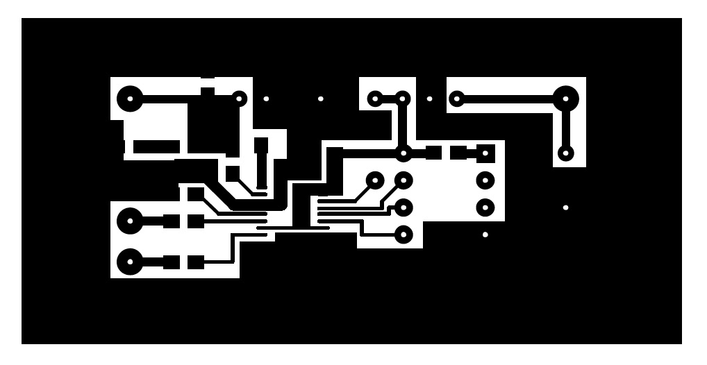
Here the component layout is shown, seen from the solderside. The Atmel, 78L05 and some decoupling 100n and 10uF elco’s are soldered on the component side. It is convenient to use a socket for the Atmel, although it is possible to (re)program it on the pcb. To do that, you need to solder 5 wires to the socket for MISO, MOSI, SCK, Reset en ground.
The software to program the pll is very straightforward. It is developped in C using AVRStudio4 and I use Ponyprog2.08 to program the chip.